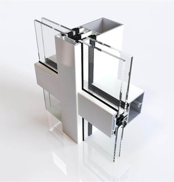
Fully tried-and-tested with endless possibilities: Schüco FW 60+ – the façade system
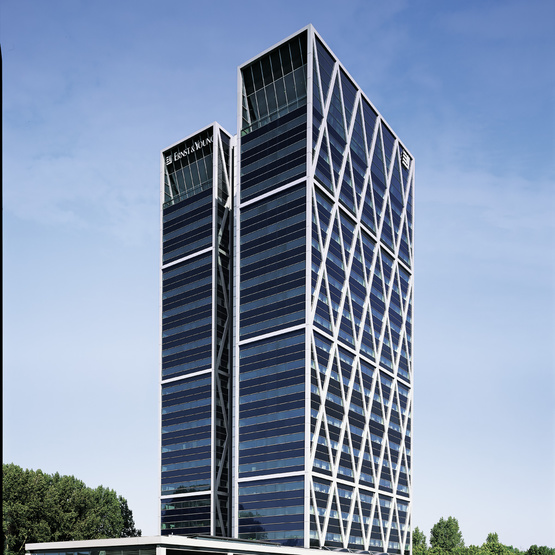
The Schüco Façade FW 60+ systems allow façades and skylights of very varied design to be constructed efficiently and reliably. Their compatibility with many other Schüco systems make Schüco FW 60+ two of the best-selling façade systems in Europe.
- From passive house-certified SI façades with maximum thermal insulation through to standard thermal insulation, the FW 60+ systems offer the right solution for every scenario and all climate regions
- Geometrically complex skylight constructions can be easily constructed
- A wide range of cover caps offer outstanding design options for a variety of façade styles
- Bullet resistance, burglar resistance and blast resistance options
- Can also be used as a fire-resistant façade (BF)
- Electric cables are concealed within the façade system, but can be accessed for inspection
| System / Material | Aluminum |
| Energy | Thermally insulated |
| Façade type | Transom-mullion |
| Uf value (>=) | 1.6 |
| Max. glass thickness | 64 mm |
| Min. face width | 60 mm |
| Poids maximum | 680 kg |
| Structural analysis | 7483,6 cm4 |
| Approvals Burglar resistance | RC3 |
| Bullet resistance | FB4 |
| Wind load resistance | PN1600-PE2400 |
| Air permeability | A4 |
| Watertightness | RE1200 |
| Impact resistance | I5 / E5 |
| Safety barrier loading | Fully suitable for safety barrier loading |
| Wind load resistance | Permitted load (<=) 2.0 kN/m²; increased 3.0k N/m² |
PREVIEW SPECIFICATION
Schüco FW 60+.HI, highly thermally insulated aluminium add-on construction on a steel load-bearing structure
(with brackets)
As a mullion/transom construction for multi-storey façades with a 60 mm external face width.
Design features:
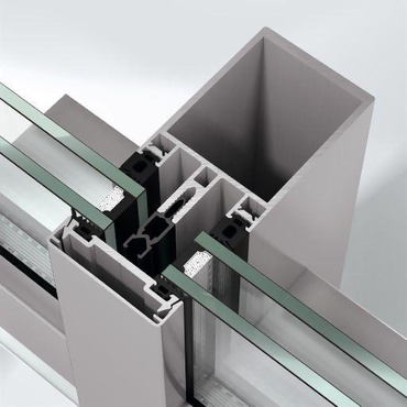
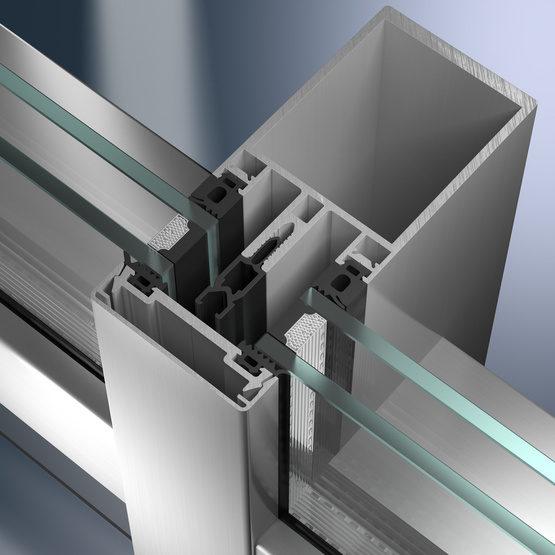
The construction must have HI isolators (isolator with foam profile) to suit the infill thicknesses. The aluminium pressure plates also have additional thermal insulation tape.
Load-bearing structure:
Selection
The load-bearing structure of the façade construction must be fabricated from steel rectangular profiles/steel supports.
Or
The load-bearing structure of the façade construction is to be fabricated from steel rectangular profiles/steel supports supplied by the customer.
End
The load-bearing steel construction is on the inside. The welded construction must be calculated and executed in accordance with DIN 18 800. The corrosion protection of steel structures must be in accordance with DIN 55 928. The steel profiles must be prepared for paint to be applied by others. The contractor for the painting work must be advised that the profile surfaces must be cleaned and primed before being painted. The space between the load-bearing structure and the add-on construction must be closed off using a gasket.
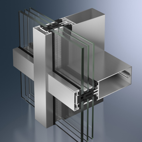
The glazing system is formed by mullion and transom profiles with C-shaped locating grooves for attachment to the load-bearing structure, as well as aluminium cover caps and/or pressure plates. The gasket locating groove of the transoms overlaps the gasket locating groove of the mullions. The overlap area must be sealed with appropriate seals. The glazing system is attached to the load-bearing structure by means of stainless steel fixing brackets. The maximum fixing intervals must be calculated in accordance with the system manufacturer’s size tables.
Glazing / insert units:
All glazing, even in the insert units, lies in the same plane.
The glazing gaskets made from weather-resistant, black EPDM on the room side are of different depths in the mullions and transoms (6 mm offset).
Two individual gaskets made from weather-resistant, black EPDM, with a height of 5 mm, are positioned on the outside. Moulded gasket intersections made from EPDM must be used where mullions and transoms join.
In principle two individual gaskets and butyl tape must be used for roof glazing.
Ventilation:
Rebate base ventilation and vapour pressure equalisation are achieved at all four corners of each module field into the mullion rebate.
For field drainage and ventilation, appropriate openings must be made in the aluminium pressure plates, cover caps and gaskets.
Profile face widths:
Mullion, transom, cover caps 60 mm
Profile basic depths:
Add-on mullion 22 mm
Add-on transom 28 mm
Cover cap (mullion) rectangular 20 mm
Cover cap (transom) rectangular 15 mm