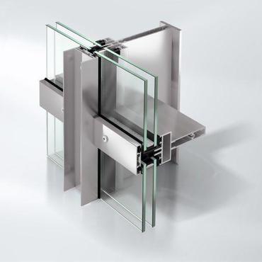
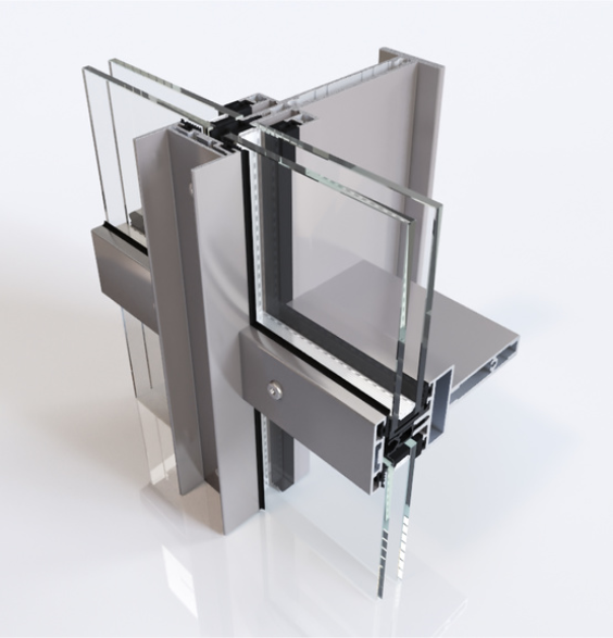
Schüco Façade FW 50+ S for slimline architectural façades in an elegant steel look.
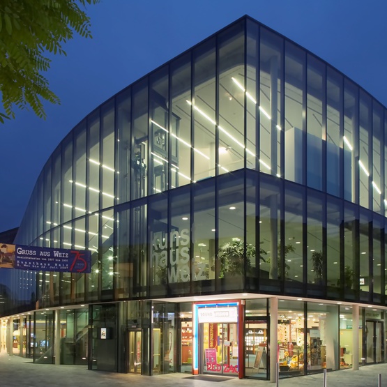
The load-bearing profiles of this thermally insulated mullion / transom construction give a slender steel appearance to large-scale profile façades as well as foyers and entrance halls.
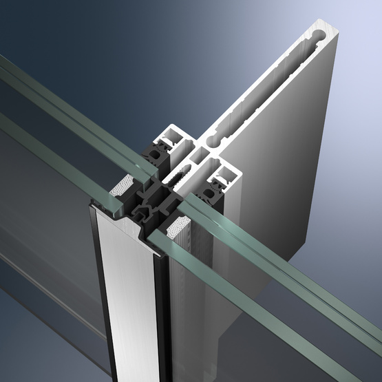
- The design has an elegant appearance due to the I and T-shaped load-bearing profiles
- Steel U-shaped pressure plates with visible screw fixings emphasise the technical character of the system
- Transom and mullion profiles are available in graduated dimensions to meet varying structural requirements
| System / Material | Aluminum |
| Energy | Highly thermally insulated Thermally insulated |
| Design | Steel look |
| Façade type | Transom-mullion |
| Uf value (>=) | 0.7 |
| Max. glass thickness | 64 mm |
| Min. face width | 50 mm |
| Poids maximum | 700 kg |
| Structural analysis | 7160,6 cm4 |
| Approvals Burglar resistance | RC3 |
| Bullet resistance | FB4 |
| Wind load resistance | PN1200-PE1800 |
| Air permeability | AE900 |
| Watertightness | RE1200 |
| Surface finishes | Powder / Anodised / Paint / Duraflon / Colour ranges |
PREVIEW SPECIFICATION
Schüco FWS 50 S, thermally insulated self-supporting aluminium façade system, with I / T-shaped profile geometry
As a mullion/transom construction for a multi-storey façade
Design features:
The construction must be sealed from outside using aluminium pressure plates to suit the infill thicknesses.
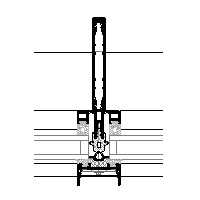
Load-bearing structure:
The load-bearing structure of the façade construction consists of rectangular multi-chamber hollow profiles.
The load-bearing profiles are located on the room side.
All profile edges are rounded.
The transom profiles are notched and overlap the mullions where they intersect, so that any moisture is reliably drained away.
On multi-storey façades, all horizontal joints must be constructed using the joint connectors and joint tolerance seals belonging to the system.
Appropriate system-based aluminium insert profiles and half profiles, as well as expansion joint seals, must be used for vertical expansion and assembly joints
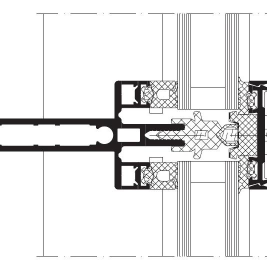
Glazing / insert units:
All glazing, even in the insert units, lies in the same plane.
The glazing gaskets made from weather-resistant, black EPDM on the room side are of different depths in the mullions and transoms (6 mm offset).
Two individual gaskets made from weather-resistant, black EPDM, with a height of 5 mm, are positioned on the outside. Cruciform gaskets made from EPDM must be used where mullions and transoms join.
In principle two individual gaskets and butyl tape must be used on faceted areas and for roof glazing.
Ventilation:
Rebate base ventilation and vapour pressure equalisation take place at all four corners of each module field into the mullion rebate.
For field drainage and ventilation, appropriate openings must be made in the aluminium pressure plates, cover caps and gaskets.
Profile face widths:
Mullion, double T-shaped contour 50/15 mm
Transom 50/15 mm
Profile basic depths:
I-shaped mullions 125-175 mm
T-shaped mullions 125-250 mm
Transoms 21-130 mm
Cover cap (mullion) U-shaped 30 mm
Cover cap (transom) rectangular 8.5 mm
The profile basic depths must be offered in accordance with the structural requirements and the plan specifications. However, note that a uniform mullion depth is required for all units. Furthermore, the transoms must have the same depth as the mullions.